
We continue our journey on NSX adding other pieces to our installation.
Let’s define the Transport Zones to which we are going to connect the transport nodes and edges. Normally two Transport Zones are defined.
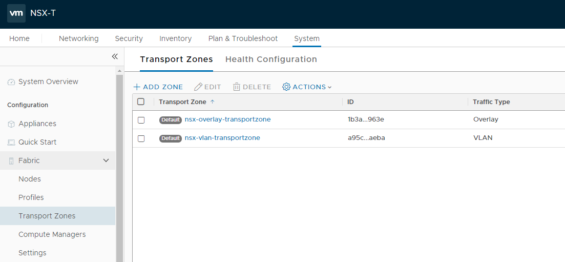
Connect to the Manager console and move to System -> Fabric -> Transport Zones.
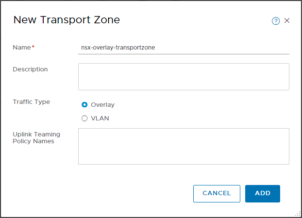
Select + ADD ZONE and create an Overlay transport zone.
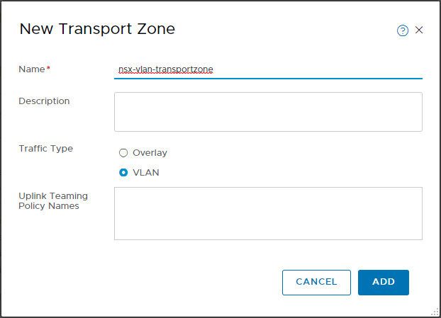
In the same way we also create a transport zone of type VLAN.
In the summary we will now have our two Transport Zones.
Proceed to create uplink profiles to be used on transport nodes and edges.
Go to System -> Fabric -> Profiles, select + to add new profiles.
Enter the name of the profile and complete the Teamings section specifying the Teaming Policy and Uplinks.
This is the profile for transport nodes (ESXi)
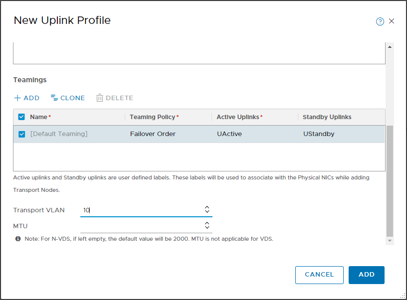
By default the Teaming Policy Failover is proposed, I have specified the name of the two uplinks (they will be used later in the configuration of the transport nodes).
Add the VLAN that will be used to transport the overlay traffic.
Also create the profile for the edges.
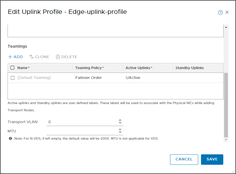
In this case I have not configured the standby uplink and the transport VLAN, the edges are virtual appliances connected to port groups. The redundancy and tagging of the VLANs is delegated to the VDS.
Define IP Pools to be used for VTEP assignment to edges and transport nodes.
Go to Networking -> IP Management -> IP Address Pools and select ADD IP ADDRESS POOL.
Specify the name and define the subnet.
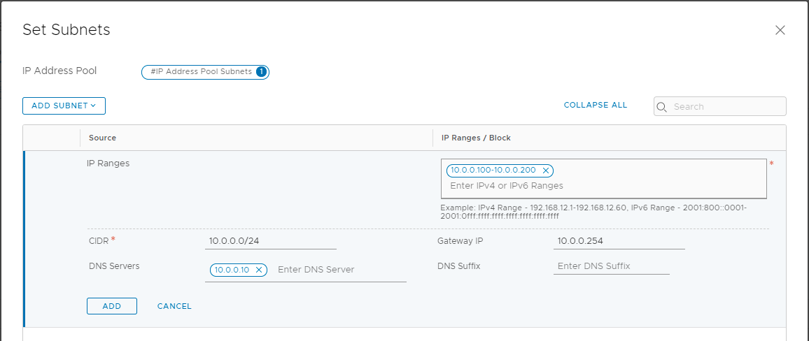
In the same way we configure the IP pool to be used for the edges, of course it will use a different subnet.
NOTE: the two newly configured subnets must be routed between them and allow an MTU of at least 1600. This is to allow connectivity between transport nodes and edges.
We now have all the elements to configure Edges and Transport nodes 🙂